
Page 152 - Build Your Own Combat Robot
P. 152
Chapter 7:
Controlling Your Motors
competing robots between the batteries and drive and weapons motors. The manual 133
switch must be rated to safely handle the current that will pass through the switch,
which can be more than 100 amps. Team Delta (www.temadelta.com) sells several
types of manual disconnect switches, in addition to a device called a removable
link, which is a physical wire connected through a plug that can be physically
pulled out of the receptacle to break the electrical connection.
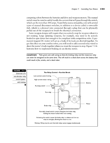
Some weapon designs will require that you actively stop the weapon when it is
not running. Large spinning weapons, for example, may need to be actively
braked to spin down fast enough to be compliant with competition rules. A per-
manent magnet DC motor will act as a brake if its leads are shorted together. To
get this effect on your combat robot, you will need to add a second relay wired to
short the motor’s leads together when you want the weapon to stop. Figure 7-5 il-
lustrates how to implement braking on an electric motor.
caution Take great care with wiring so that the braking relay and the motor-run relay
can never be energized at the same time. This will result in a dead short across the battery that
could result in fire, smoke, and a dead robot.
FIGURE 7-5
Schematic of a
one-direction relay
control system
with braking.