
Page 151 - Build Your Own Combat Robot
P. 151
Build Your Own Combat Robot
132
How It All Works Together
Controlling a motor with a relay is accomplished via a simple circuit. A wire runs
from the battery connection, through the manual disconnect switch, to one side of
the relay contact. Another wire goes from the other relay contact to one of the motor
terminals, and a final wire runs from the other motor terminal to the battery con-
nection. When the relay is energized, the contact closes and makes a complete circuit
from the battery through the motor. The relay switch can be on either the positive
or the negative side of the motor—usually, other factors of your wiring harness
design will make one way or the other more convenient.
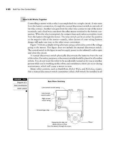
Figure 7-4 shows a simple wiring schematic using a solenoid to control the voltage
going to the motor. This figure does not include the manual disconnect switch.
The control switch in the figure is used to supply power to the solenoid’s coil to open
and close the circuit.
A manual disconnect switch physically disconnects the batteries from the rest
of the robot. For safety purposes, a disconnect switch should be placed in all combat
robots. You do not want the robot to be accidentally turned on by you or another
person while you’re working on the robot; and sometimes a short can occur during
maintenance, which will cause a motor to turn.
Many robot contests, such as BattleBots, Robot Wars, and Robotica, require
that a manual disconnect switch (sometimes called a kill switch) be installed in all
FIGURE 7-4
Diagram of a
basic one-direction
motor control.