
Page 100 - Build Your Own Quadcopter_ Power Up Your Designs with the Parallax Elev-8
P. 100
Chapter 4: Prog ramming the P arallax Propeller Chip 79
The first line of the code is also known as the method signature. It contains the public
name of the method, which in this case, is Toggle, followed by any arguments it requires to
function properly. There are three arguments—namely, Pin, Delay, and Count. Pin is an
integer that represents the number of the GPIO pin that controls the LED. In our example,
pins 14 and 15 are being used. Thus, it becomes immediately obvious that the Toggle method
must be called twice to accommodate the two different pins.
The next argument is named Delay, and it is also an integer that represents a time delay
in terms of actual clock cycles. There are two different delays used in the Blinker1 program,
one with a 6_000_000 value and the other with a 4_000_000 value. I am sure you could not
help but notice that underscores are used in lieu of commas for delimiters. I believe they are
optional, but using underscores does help in avoiding the entry of an incorrect number of
zeros. The actual delay time is dependent on the real Prop’s operating clock speed. The
4_000_000 delay would represent an actual delay of ∕12 seconds for a 12-MHz clock, which is
4
the default rate used in the Spin interpreter, or equivalently, ∕3 of a second, which also equals
1
333.3 ms. Just remember: the bigger the number, the longer the delay.
The last argument is the Count, which represents the number of iterations or loops
that the method performs before stopping. This sets the number of blinks, while Delay sets
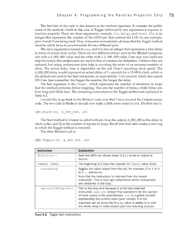
how long each blink lasts. The remaining instructions in the Toggle method are explained in
Table 4.2.
I would like to go back to the Blinker1 code now that I have covered the Output source
code. The two calls in Blinker1 should now make a little more sense to you. The first one is:
LED.Start(14, 6_000_000, 20)
The Start method in Output is called with pin 14 as the output, 6_000_000 as the delay in
clock cycles, and 20 as the number of repeats or loops. Recall that Start also creates a new cog
in which the Toggle method is executed.
The other Blinker1 call is:
LED.Toggle(15, 4_000_000, 40)
Instruction Explanation
dira[Pin]~~ Sets the GPIO pin whose value is Pin to be an output or
source.
repeat Count The beginning of a loop that repeats for Count value times.
!outa[Pin] Toggles the value output from the pin, for example, 0 to 1 to 0
to 1 ... and so on.
Note that the instruction is indented from the repeat
instruction. This is how Spin determines which instructions
are contained in the loop.
waitcnt(Delay+cnt) This is the loop end because it is the last indented
instruction. waitcnt delays Prop operations for the number
of clock cycles in the parentheses. cnt is a global variable
representing the current clock cycle number. It is not
important per se since the Delay value is added to it, and
the whole delay is really based upon the resulting amount.
Table 4.2 Toggle Spin Instructions