
Page 101 - Build Your Own Quadcopter_ Power Up Your Designs with the Parallax Elev-8
P. 101
80 Bu il d Y o ur O w n Q u a d c o p t e r
Here the Toggle method in Output is called directly with pin 15 as the output, 4_000_000
as the delay, and 40 as the number of loops. No new cog is created when Toggle is directly
called so this instruction uses the existing cog that was started with Blinker1 or cog #0.
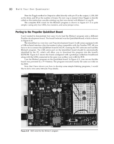
The complete BOE wired for the Blinker1 program is shown in Figure 4.9. It is quite
simple—using only two LEDs, two resistors, and some jumper wires.
Porting to the Propeller QuickStart Board
I next wanted to demonstrate how easy it is to load the Blinker1 program onto a different
Parallax development board. The board I selected was the QuickStart board, which is shown
in Figure 4.10.
The QuickStart is a very low-cost Prop development board. It still comes equipped with
a USB-to-Serial interface chip that makes it plug compatible with the Parallax PST. All you
have to do is connect the QuickStart board to the PC running the PST software and load the
Blinker1 program. The USB comm port on the QuickStart board should be automatically
identified by the PC, which will allow you to download the program into the board’s
EEPROM. Figure 4.11 shows the board configured with a prototype solderless breadboard
along with the LEDs connected in the same way as they were with the BOE.
I ran the Blinker1 program on the QuickStart board. In Figure 4.11, you can see that the
board was powered by a 9-V battery. The program executed exactly the same as it did on
the BOE.
Now that I have shown you how to develop some simple blinking programs, I would
like to delve into some intricate Prop details.
Figure 4.9 BOE wired for the Blinker1 program.