
Page 97 - Build Your Own Quadcopter_ Power Up Your Designs with the Parallax Elev-8
P. 97
76 Bu il d Y o ur O w n Q u a d c o p t e r
There are four separate views that may be selected in the PST by clicking on any of the
radio buttons located at the top of the Editor pane. You should notice that the Full Source
button is selected in Figure 4.5, while the Documentation button is selected in Figure 4.6.
Condensed and Summary are the two other views that are available, but they generate very
limited information, as compared to the Full Source or Documentation views for this small
program. I would imagine that Condensed or Summary views might be useful for very large
projects containing many objects with much more corresponding source code.
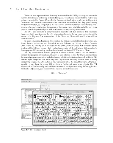
The PST also contains a comprehensive character set that includes the schematic
fragments that I used to create the LED schematics shown in the top comment section of the
source code. Figure 4.7 is a screenshot of the Character Chart with the Horizontal Line
symbol selected.
To insert schematic characters, first position the Editor prompt at the location where you
desire them to be inserted and then click on Help followed by clicking on Show Character
Chart. Next, by clicking on a character in the chart, you will place that character at the
location of the Editor’s prompt that you had previously set. It just takes a little practice to
develop your skill at creating small-scale schematics with the PST Character Chart.
The OBJ section in the Blinker1 program is where additional objects that are needed to
support the program are declared. Blinker1 is also referred to as a Top Object, as it contains
the start of program execution and also has any additional objects referenced within its OBJ
section. Spin programs can have only one Top Object but may contain zero to many
supporting objects. The OBJ section is how Spin establishes the object hierarchy. Other non-
top objects may have their own OBJ sections to further reference more objects. The PST
keeps track of this hierarchy and will issue an error if an object is missing. Referring back to
Blinker1’s OBJ section, you can see that it has one line in the section:
LED : “Output”
Figure 4.7 PST character chart.