
Page 243 - Build Your Own Quadcopter_ Power Up Your Designs with the Parallax Elev-8
P. 243
222 Bu il d Y o ur O w n Q u a d c o p t e r
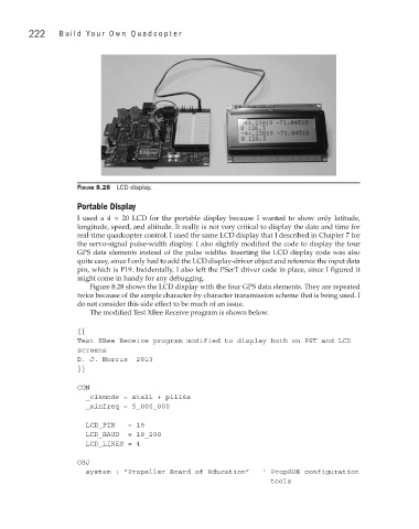
Figure 8.28 LCD display.
Portable Display
I used a 4 × 20 LCD for the portable display because I wanted to show only latitude,
longitude, speed, and altitude. It really is not very critical to display the date and time for
real-time quadcopter control. I used the same LCD display that I described in Chapter 7 for
the servo-signal pulse-width display. I also slightly modified the code to display the four
GPS data elements instead of the pulse widths. Inserting the LCD display code was also
quite easy, since I only had to add the LCD display-driver object and reference the input data
pin, which is P19. Incidentally, I also left the PSerT driver code in place, since I figured it
might come in handy for any debugging.
Figure 8.28 shows the LCD display with the four GPS data elements. They are repeated
twice because of the simple character-by-character transmission scheme that is being used. I
do not consider this side effect to be much of an issue.
The modified Test XBee Receive program is shown below.
{{
Test XBee Receive program modified to display both on PST and LCD
screens
D. J. Norris 2013
}}
CON
_clkmode = xtal1 + pll16x
_xinfreq = 5_000_000
LCD_PIN = 19
LCD_BAUD = 19_200
LCD_LINES = 4
OBJ
system : “Propeller Board of Education” ‘ PropBOE configuration
tools