
Page 238 - Build Your Own Quadcopter_ Power Up Your Designs with the Parallax Elev-8
P. 238
Chapter 8: GPS and a Real- T ime Situational Displa y 217
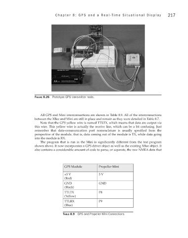
Figure 8.26 Prototype GPS transmitter node.
All GPS and Mini interconnections are shown in Table 8.9. All of the interconnections
between the XBee and Mini are still in place and remain as they were detailed in Table 8.7.
Note that the GPS yellow wire is named TTLTX, which means that data are output via
this wire. This yellow wire is actually the receive line, which can be a bit confusing. Just
remember that data-communication port nomenclature is usually specified from the
perspective of the module, that is, data coming out of the module is TX, while data going
into the module is RX.
The program that is run in the Mini is significantly different from the test program
shown above. It now incorporates a GPS driver object as well as the existing XBee object. It
also contains a considerable amount of code to parse, or separate, the raw NMEA data that
GPS Module Propeller Mini
+5 V 5 V
(Red)
GND GND
(Black)
TTLTX P8
(Yellow)
TTLRX P9
(Blue)
Table 8.9 GPS and Propeller Mini Connections