
Page 237 - Build Your Own Quadcopter_ Power Up Your Designs with the Parallax Elev-8
P. 237
216 Bu il d Y o ur O w n Q u a d c o p t e r
XBee Range Check
I performed a simple range check to determine the approximate operating range for the XBee
test system. The transmitter node was set on a tripod at one end of a large, open field. I then
walked away from the transmitter while carrying a laptop running the test program.
I walked approximately 114 paces from the transmitter, at which point the transmission
became intermittent. My pace is about one meter, so that was a good estimate for the reliable
range. I walked a bit further and continually repositioned the receiver node to see if the
signal could be reacquired. I was able to go out to about 154 m, at which point no amount of
node juggling could get the signal back. The 114-m distance is actually a bit better than the
stated 100-m range in the Zigbee specification.
Digi International also manufactures a line they call the XBee Pro, which generates up to
60 mW of power—much greater than the regular Series 1 power output of 1 mW. The Pro
brochure claims a line-of-sight range of up to one mile. That is an impressive range, but I am
fairly sure that it would far exceed the range of the R/C transmitter and the FPV camera
system, which will be discussed in the next chapter. In any case, I believe that the quadcopter
would be invisible to the operator at such a distance, which is never a good idea.
The range check confirmed that the XBee modules appropriately support operations at
or below 300 feet when they are above ground and reasonably close to the operator’s control
station.
Complete GPS System
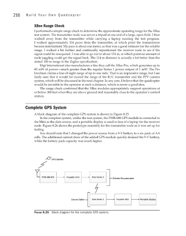
A block diagram of the complete GPS system is shown in Figure 8.25.
In the complete system, unlike the test system, the PMB-688 GPS module is connected to
the Mini as the data source, and a portable display is used in lieu of a laptop for the receiver
node. Figure 8.26 shows the prototype assembly for the transmitter node as it was set up for
testing.
You should note that I changed the power source from a 9-V battery to a six pack of AA
cells. The additional current draw of the added GPS module quickly drained the 9-V battery,
while the battery pack capacity was much higher.
Figure 8.25 Block diagram for the complete GPS system.