
Page 234 - Build Your Own Quadcopter_ Power Up Your Designs with the Parallax Elev-8
P. 234
Chapter 8: GPS and a Real- T ime Situational Displa y 213
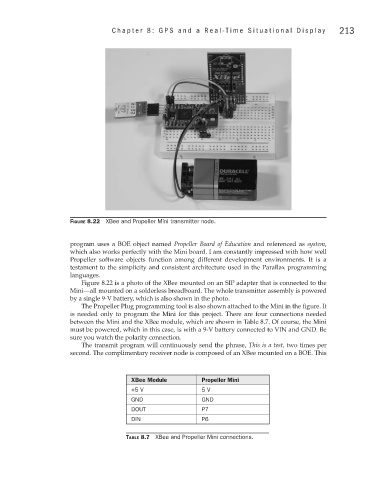
Figure 8.22 XBee and Propeller Mini transmitter node.
program uses a BOE object named Propeller Board of Education and referenced as system,
which also works perfectly with the Mini board. I am constantly impressed with how well
Propeller software objects function among different development environments. It is a
testament to the simplicity and consistent architecture used in the Parallax programming
languages.
Figure 8.22 is a photo of the XBee mounted on an SIP adapter that is connected to the
Mini—all mounted on a solderless breadboard. The whole transmitter assembly is powered
by a single 9-V battery, which is also shown in the photo.
The Propeller Plug programming tool is also shown attached to the Mini in the figure. It
is needed only to program the Mini for this project. There are four connections needed
between the Mini and the XBee module, which are shown in Table 8.7. Of course, the Mini
must be powered, which in this case, is with a 9-V battery connected to VIN and GND. Be
sure you watch the polarity connection.
The transmit program will continuously send the phrase, This is a test, two times per
second. The complimentary receiver node is composed of an XBee mounted on a BOE. This
XBee Module Propeller Mini
+5 V 5 V
GND GND
DOUT P7
DIN P6
Table 8.7 XBee and Propeller Mini connections.