
Page 229 - Build Your Own Quadcopter_ Power Up Your Designs with the Parallax Elev-8
P. 229
208 Bu il d Y o ur O w n Q u a d c o p t e r
Features/Specifications Description
Frequency/modulation O-QPSK data in 5.0 MHz channels and full spread-spectrum
encode and decode (modified DSSS)
Operates on one of 16 selectable channels in the 2.4 GHz
ISM band
Maximum bandwidth 250 kbps (compatible with the 802.15.4 Standard)
Receiver sensitivity <- 92 dBm (typical) at 1.0% packet error rate
Maximum output power 0 dBm nominal, programmable from -27 dBm to 4 dBm
Power supply 2.0 to 3.4 V
Power conservation modes < 1 μA Off current
1 μA Typical hibernate current
35 μA Typical doze current (no CLKO)
Timers/comparators Four internal timer comparators available to supplement
MCU resource
Clock outputs Programmable frequency clock output (CLKO) for use by MCU
Number of GPIO pins 7
Internal oscillator 16 MHz with onboard trim capability
Operating temperature range - 40 to 85°C
Package size QFN-32 Small form factor (SFF)
™
Table 8.5 Freescale MC13192 Features and Specifications
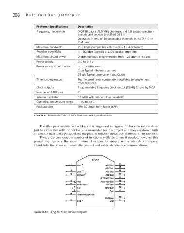
The XBee pins are detailed in a logical arrangement in Figure 8.18 for your information.
Just be aware that only four of the pins are needed for this project, and they are shown with
an asterisk next to the pin label. All the pin and function descriptions are shown in Table 8.6.
There are a considerable number of functions available to you if needed; however, this
project requires only the most minimal functions for simple and reliable data transfers.
Thankfully, the XBees automatically connect and establish reliable communications.
Figure 8.18 Logical XBee pinout diagram.