
Page 226 - Build Your Own Quadcopter_ Power Up Your Designs with the Parallax Elev-8
P. 226
Chapter 8: GPS and a Real- T ime Situational Displa y 205
Features/Specifications Description
Voltage requirements Regulated 6.5–12 V DC through the VIN pin
Communication Mini USB, the Propeller Plug required for programming
(#32210, not included)
Dimensions 0.81 × 1.52 in (20.5 × 38.6 mm)
Power outputs 3.3 V DC regulated output @ 400 mA max
5 V DC regulated output @ 600 mA max
Operating temp range -40°F to +185°F (-40°C to +85°C)
GPIO pins 19, P0 to P18
Table 8.4 Key Details and Specifications for the Parallax Propeller Mini Module
Key details and specifications for the Mini are shown in Table 8.4. I mounted the Mini on
a solderless breadboard to gain easy access to all the general-purpose input/output (GPIO)
pins. The breadboard will also allow for easy mounting and connections to both the GPS
receiver and the XBee transceiver, which is discussed in the following section.
Radio-Frequency Transceiver Module
GPS data must be sent wirelessly from the quadcopter to a ground station where it is received
and displayed for the operator’s use. I selected XBee transceivers to perform this function,
since they are small, lightweight, inexpensive, and totally compatible with the other modules
used in this project. XBee is the brand name for a series of digital RF transceivers manufactured
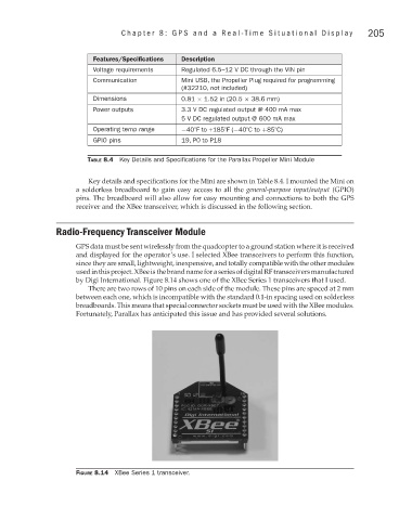
by Digi International. Figure 8.14 shows one of the XBee Series 1 transceivers that I used.
There are two rows of 10 pins on each side of the module. These pins are spaced at 2 mm
between each one, which is incompatible with the standard 0.1-in spacing used on solderless
breadboards. This means that special connector sockets must be used with the XBee modules.
Fortunately, Parallax has anticipated this issue and has provided several solutions.
Figure 8.14 XBee Series 1 transceiver.