
Page 221 - Build Your Own Quadcopter_ Power Up Your Designs with the Parallax Elev-8
P. 221
200 Bu il d Y o ur O w n Q u a d c o p t e r
The TTL in the pin designations represents the fact that the logic levels are 0 and 5 V for
low and high levels respectively. The GPS receiver also uses a 9600-baud rate to communicate
with the controlling microprocessor to both receive and transmit data back and forth. There
is no need for a separate clock signal line, since the UART protocol is designed to be self-
clocking.
CautioN: To ensure communications with the Prop Mini module, connect the GPS TX lead to the
Mini’s P8 pin, and likewise, connect the GPS RX lead to the Mini’s P9 pin. Misconnecting these
pins will likely not cause any damage, but you will not have data communications between the
GPS receiver and the Propeller Mini module.
Initial GPS Receiver Test
It would be wise to check that the PMB-688 GPS receiver is functioning as expected before
going on to later stages in this project. Ensure that you have a good line of sight with the
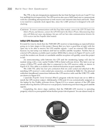
open sky to be able to receive the GPS satellite signals. I used an external GPS antenna
because my test setup was indoors and had no reliable satellite reception. Parallax has an
external GPS antenna available (part number 28502) that is shown in Figure 8.9 and is well
worth the modest cost. Erratic or unreliable satellite reception will quickly cause this project
to fail.
An interconnecting cable between the GPS and the monitoring laptop will also be
needed along with a very useful Prolific USB-to-Serial software driver. The link is set up
using a USB-to-TTL serial cable that is connected to the GPS receiver cable, as shown in
Figure 8.10. This cable is available from Adafruit Industries as part number 954.
The USB/TTL cable has four pin connectors that are color coded and attached to the
matching GPS receiver’s color-coded pin connectors, as detailed in Table 8.2. The physical
solderless breadboard connections between the GPS receiver cable and the USB/TTL cable
are shown in Figure 8.11.
I used the Propeller Serial Terminal (PSerT) program with the baud rate set to 4800 to
match the GPS receiver output. Additionally, COM port 44 was automatically assigned on
the laptop by the Prolific software driver. Figure 8.12 is a screen capture of the GPS data
stream showing that the GPS receiver was properly functioning and receiving good satellite
signals.
Completing the above steps confirms that the PMB-688 GPS receiver is operating
properly, which is a prerequisite before further project development. You are almost ready to
Figure 8.9 External GPS Antenna (PMB-688).