
Page 233 - Build Your Own Quadcopter_ Power Up Your Designs with the Parallax Elev-8
P. 233
212 Bu il d Y o ur O w n Q u a d c o p t e r
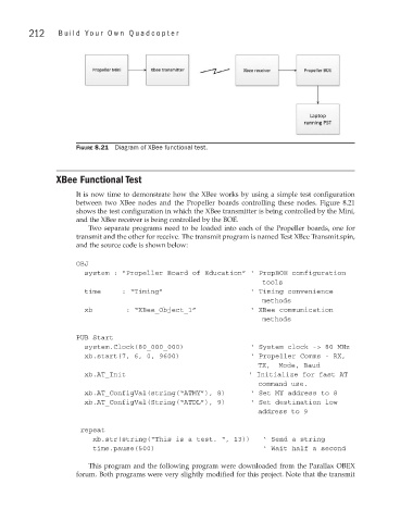
Figure 8.21 Diagram of XBee functional test.
XBee Functional Test
It is now time to demonstrate how the XBee works by using a simple test configuration
between two XBee nodes and the Propeller boards controlling these nodes. Figure 8.21
shows the test configuration in which the XBee transmitter is being controlled by the Mini,
and the XBee receiver is being controlled by the BOE.
Two separate programs need to be loaded into each of the Propeller boards, one for
transmit and the other for receive. The transmit program is named Test XBee Transmit.spin,
and the source code is shown below:
OBJ
system : “Propeller Board of Education” ‘ PropBOE configuration
tools
time : “Timing” ‘ Timing convenience
methods
xb : “XBee_Object_1” ‘ XBee communication
methods
PUB Start
system.Clock(80_000_000) ‘ System clock -> 80 MHz
xb.start(7, 6, 0, 9600) ‘ Propeller Comms - RX,
Baud
xb.AT_Init ‘ Initialize for fast AT
xb.AT_ConfigVal(string(“ATMY”), 8) ‘ Set MY address to 8
xb.AT_ConfigVal(String(“ATDL”), 9) ‘ Set destination low
9
repeat
xb.str(string(“This is a test. “, 13)) ‘ Send a string
time.pause(500) ‘ Wait half a second
This program and the following program were downloaded from the Parallax OBEX
forum. Both programs were very slightly modified for this project. Note that the transmit