
Page 45 - Build Your Own Quadcopter_ Power Up Your Designs with the Parallax Elev-8
P. 45
24 Bu il d Y o ur O w n Q u a d c o p t e r
direction. Failure to properly align the board means the gyroscope cannot accurately measure
the appropriate angular velocities, thus making quadcopter control questionable.
Raw data on each axis is sent in serial format from the gyroscope sensor to the main
processor on the flight-control board at a very fast rate. This main processor is the Parallax
Propeller chip, which will be thoroughly discussed in Chapter 4. What should be noted now
is that a great deal of information is extracted from the raw data by some very involved and
complex calculations in order to generate the appropriate motor-control speed commands
that reflect what the user wants to do with the quadcopter. There is also a good deal of
ongoing real-time filtering to ensure that only the relevant user commands are being
followed and are not being disturbed by noise.
PID Control
PID is an acronym for proportional integral derivative and is used in almost all quadcopter
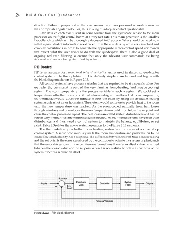
control systems. The theory behind PID is relatively simple to understand and begins with
the block diagram shown in Figure 2.13.
All control systems have process variables that are required to be at a specific value. For
example, the thermostat is part of the very familiar home-heating (and maybe cooling)
system. The room temperature is the process variable in such a system. We could set a
temperature on the thermostat, and if that value was higher than the actual room temperature,
the thermostat would direct the furnace to heat the room by using the available heating
system (such as hot air or hot water). The system would continue to provide heat to the room
until the new temperature was reached. As the room cooled naturally from heat losses
through windows and open doors, the room temperature would drop below the set point and
cause the control process to repeat. The heat losses are called system disturbances and are the
reason why the thermostatic-control system is needed. All real-world systems have their own
disturbances, and thus, need a control system to maintain the balance, equilibrium, or set
point. Table 2.3 relates the above system operation to the Figure 2.13 elements.
The thermostatically controlled room heating system is an example of a closed-loop
control system. A sensor continuously reads the room temperature and provides this to the
controller, which already has a set point. The difference between the real-time sensor reading
and the set point is the error signal used by the controller to actuate the system or plant, such
that the error drives toward a zero difference. Sometimes there is an offset value permitted
between the sensor value and the set point when it is not realistic to obtain a zero error or the
system functions require an offset.
Figure 2.13 PID block diagram.