
Page 66 - Build Your Own Quadcopter_ Power Up Your Designs with the Parallax Elev-8
P. 66
Chapter 3: Building the Ele v-8 45
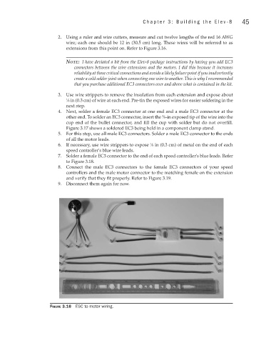
2. Using a ruler and wire cutters, measure and cut twelve lengths of the red 16 AWG
wire; each one should be 12 in (30.5 cm) long. These wires will be referred to as
extensions from this point on. Refer to Figure 3.16.
note: I have deviated a bit from the Elev-8 package instructions by having you add EC3
connectors between the wire extensions and the motors. I did this because it increases
reliability at these critical connections and avoids a likely failure point if you inadvertently
create a cold solder joint when connecting one wire to another. This is why I recommended
that you purchase additional EC3 connectors over and above what is contained in the kit.
3. Use wire strippers to remove the insulation from each extension and expose about
1 ∕8 in (0.3 cm) of wire at each end. Pre-tin the exposed wires for easier soldering in the
next step.
4. Next, solder a female EC3 connector at one end and a male EC3 connector at the
other end. To solder an EC3 connector, insert the ∕8-in exposed tip of the wire into the
1
cup end of the bullet connector, and fill the cup with solder but do not overfill.
Figure 3.17 shows a soldered EC3 being held in a component clamp stand.
5. For this step, use all male EC3 connectors. Solder a male EC3 connector to the ends
of all the motor leads.
6. If necessary, use wire strippers to expose ∕8 in (0.3 cm) of metal on the end of each
1
speed controller's blue wire leads.
7. Solder a female EC3 connector to the end of each speed controller's blue leads. Refer
to Figure 3.18.
8. Connect the male EC3 connectors to the female EC3 connectors of your speed
controllers and the male motor connector to the matching female on the extension
and verify that they fit properly. Refer to Figure 3.19.
9. Disconnect them again for now.
Figure 3.16 ESC to motor wiring.