
Page 86 - Build Your Own Quadcopter_ Power Up Your Designs with the Parallax Elev-8
P. 86
Chapter 3: Building the Ele v-8 65
The propeller is mounted on a steel rod that is effectively suspended between two very
strong magnets. One end of the rod contacts a magnet, while there is a ∕32-in (0.1-cm) gap
1
between the other rod end and the other magnet. You can barely see this gap on the left side
of the rod in the figure. This method of suspending the rod is practically free of friction and
allows the propeller to swing freely so that the heavier side always swings down. I very (and
I mean very) lightly sanded the back side off the propeller’s heavy side until the propeller no
longer had a heavy side. I took the propeller off the balancer, sanded a little bit, and then put
the balancer back in until it no longer rotated downward. This is a tedious process but well
worth the effort.
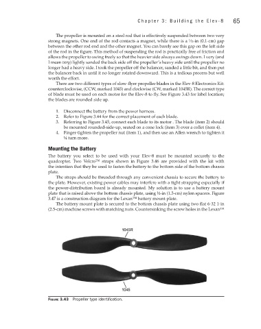
There are two different types of slow-flyer propeller blades in the Elev-8 Electronics Kit:
counterclockwise, (CCW, marked 1045) and clockwise (CW, marked 1045R). The correct type
of blade must be used on each motor for the Elev-8 to fly. See Figure 3.43 for label location;
the blades are rounded side up.
1. Disconnect the battery from the power harness.
2. Refer to Figure 3.44 for the correct placement of each blade.
3. Referring to Figure 3.45, connect each blade to its motor . The blade (item 2) should
be mounted rounded-side-up, seated on a cone lock (item 3) over a collet (item 4).
4. Finger-tighten the propeller nut (item 1), and then use an Allen wrench to tighten it
¼ turn more.
Mounting the Battery
The battery you select to be used with your Elev-8 must be mounted securely to the
quadcopter. Two Velcro™ straps shown in Figure 3.46 are provided with the kit with
the intention that they be used to fasten the battery to the bottom side of the bottom chassis
plate.
The straps should be threaded through any convenient chassis to secure the battery to
the plate. However, existing power cables may interfere with a tight strapping especially if
the power-distribution board is already mounted. My solution is to use a battery mount
plate that is raised above the bottom chassis plate, using ½-in (1.3-cm) nylon spacers. Figure
3.47 is a construction diagram for the Lexan™ battery mount plate.
The battery mount plate is secured to the bottom chassis plate using two flat 6-32 1-in
(2.5-cm) machine screws with matching nuts. Countersinking the screw holes in the Lexan™
Figure 3.43 Propeller type identification.