
Page 84 - Build Your Own Quadcopter_ Power Up Your Designs with the Parallax Elev-8
P. 84
Chapter 3: Building the Ele v-8 63
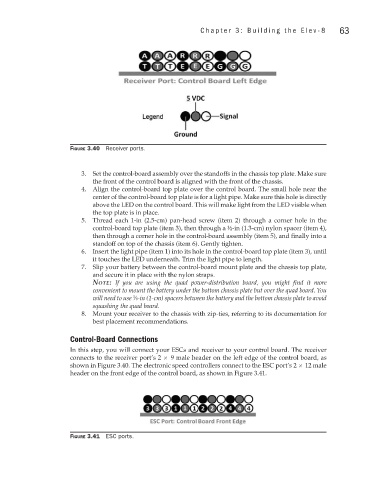
Figure 3.40 Receiver ports.
3. Set the control-board assembly over the standoffs in the chassis top plate. Make sure
the front of the control board is aligned with the front of the chassis.
4. Align the control-board top plate over the control board. The small hole near the
center of the control-board top plate is for a light pipe. Make sure this hole is directly
above the LED on the control board. This will make light from the LED visible when
the top plate is in place.
5. Thread each 1-in (2.5-cm) pan-head screw (item 2) through a corner hole in the
control-board top plate (item 3), then through a ½-in (1.3-cm) nylon spacer (item 4),
then through a corner hole in the control-board assembly (item 5), and finally into a
standoff on top of the chassis (item 6). Gently tighten.
6. Insert the light pipe (item 1) into its hole in the control-board top plate (item 3), until
it touches the LED underneath. Trim the light pipe to length.
7. Slip your battery between the control-board mount plate and the chassis top plate,
and secure it in place with the nylon straps.
note: If you are using the quad power-distribution board, you might find it more
convenient to mount the battery under the bottom chassis plate but over the quad board. You
will need to use ∕8-in (1-cm) spacers between the battery and the bottom chassis plate to avoid
3
squashing the quad board.
8. Mount your receiver to the chassis with zip-ties, referring to its documentation for
best placement recommendations.
Control-Board Connections
In this step, you will connect your ESCs and receiver to your control board. The receiver
connects to the receiver port’s 2 × 9 male header on the left edge of the control board, as
shown in Figure 3.40. The electronic speed controllers connect to the ESC port’s 2 × 12 male
header on the front edge of the control board, as shown in Figure 3.41.
Figure 3.41 ESC ports.