
Page 80 - Build Your Own Quadcopter_ Power Up Your Designs with the Parallax Elev-8
P. 80
Chapter 3: Building the Ele v-8 59
9. When you are sure your motor connections are all correct, apply heat to finish
shrinking the tubing over the motor/ESC connector joints.
10. To synchronize the ESCs, power on the Elev-8 quadcopter. Turn on your transmitter,
then set the throttle to max position. After the standard startup sequence, two
separate beeps will indicate that the max throttle position has been set and stored.
Lower the throttle to min position. You will hear three beeps, which indicate that
min throttle position has been set and stored.
Chassis Top-Plate and Control-Board Assemblies
note: I would recommend reading Chapters 7 and 8 now if you are considering installing a video
system for use with your quadcopter. Mounting the video camera frame assembly would be easier
at this point with the chassis top plate not yet installed. You certainly could continue with the
assembly without a video camera frame installation but eventually you will have to disassemble
your quadcopter back to this point if you later decide to install it.
In this step, you will prepare and attach the chassis top plate. Then, you prepare and
attach the control board to its mount plate.
note: The control board mount plate has slots around all four edges.
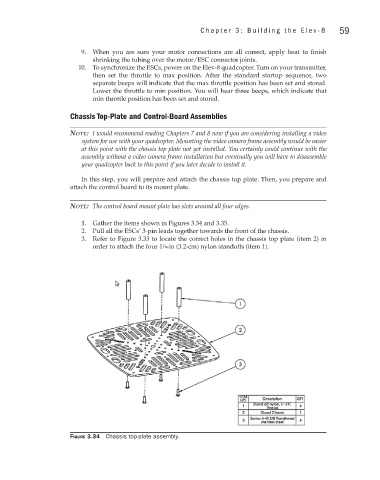
1. Gather the items shown in Figures 3.34 and 3.35.
2. Pull all the ESCs’ 3-pin leads together towards the front of the chassis.
3. Refer to Figure 3.33 to locate the correct holes in the chassis top plate (item 2) in
order to attach the four 1 ∕4-in (3.2-cm) nylon standoffs (item 1).
1
Figure 3.34 Chassis top-plate assembly.