
Page 75 - Build Your Own Quadcopter_ Power Up Your Designs with the Parallax Elev-8
P. 75
54 Bu il d Y o ur O w n Q u a d c o p t e r
3. Solder a male EC3 connector to the end of each speed controller’s red and black leads.
4. Place a ∕8-in (1.6-cm) piece of shrink tubing so that it covers the solder connection
5
but does not overlap onto the male connector.
5. note: I used red shrink tubing for the red leads and black shrink tubing for the
black leads. It is not very important to do this, yet it does lend a nice touch to the
installation.
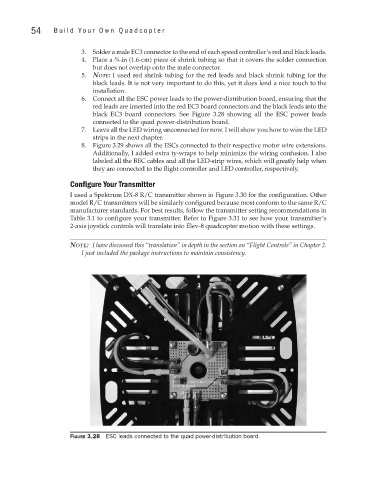
6. Connect all the ESC power leads to the power-distribution board, ensuring that the
red leads are inserted into the red EC3 board connectors and the black leads into the
black EC3 board connectors. See Figure 3.28 showing all the ESC power leads
connected to the quad power-distribution board.
7. Leave all the LED wiring unconnected for now. I will show you how to wire the LED
strips in the next chapter.
8. Figure 3.29 shows all the ESCs connected to their respective motor wire extensions.
Additionally, I added extra ty-wraps to help minimize the wiring confusion. I also
labeled all the BEC cables and all the LED-strip wires, which will greatly help when
they are connected to the flight controller and LED controller, respectively.
Configure Your Transmitter
I used a Spektrum DX-8 R/C transmitter shown in Figure 3.30 for the configuration. Other
model R/C transmitters will be similarly configured because most conform to the same R/C
manufacturer standards. For best results, follow the transmitter setting recommendations in
Table 3.1 to configure your transmitter. Refer to Figure 3.31 to see how your transmitter’s
2-axis joystick controls will translate into Elev-8 quadcopter motion with these settings.
note: I have discussed this “translation” in depth in the section on “Flight Controls” in Chapter 2.
I just included the package instructions to maintain consistency.
Figure 3.28 ESC leads connected to the quad power-distribution board.