
Page 73 - Build Your Own Quadcopter_ Power Up Your Designs with the Parallax Elev-8
P. 73
52 Bu il d Y o ur O w n Q u a d c o p t e r
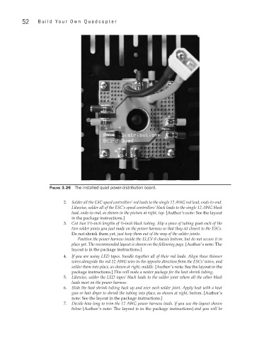
Figure 3.26 The installed quad power-distribution board.
2. Solder all the ESC speed controllers’ red leads to the single 12 AWG red lead, ends-to-end.
Likewise, solder all of the ESC’s speed controllers’ black leads to the single 12 AWG black
lead, ends-to-end, as shown in the picture at right, top. [Author’s note: See the layout
in the package instructions.]
3. Cut two 1½-inch lengths of ½-inch black tubing. Slip a piece of tubing past each of the
two solder joints you just made on the power harness so that they sit closest to the ESCs.
Do not shrink them yet, just keep them out of the way of the solder joints.
Position the power harness inside the ELEV-8 chassis bottom, but do not secure it in
place yet. The recommended layout is shown on the following page. [Author’s note: The
layout is in the package instructions.]
4. If you are using LED tapes, bundle together all of their red leads. Align these thinner
wires alongside the red 12 AWG wire in the opposite direction from the ESCs’ wires, and
solder them into place, as shown at right, middle. [Author’s note: See the layout in the
package instructions.] This will make a neater package for the heat shrink tubing.
5. Likewise, solder the LED tapes’ black leads to the solder joint where all the other black
leads meet on the power harness.
6. Slide the heat shrink tubing back up and over each solder joint. Apply heat with a heat
gun or hair dryer to shrink the tubing into place, as shown at right, bottom. [Author’s
note: See the layout in the package instructions.]
7. Decide how long to trim the 12 AWG power harness leads. If you use the layout shown
below [Author’s note: The layout is in the package instructions] and you will be