
Page 18 - Build Your Own Transistor Radios a Hobbyists Guide to High-Performance and Low-Powered Radio Circuits
P. 18
inductors are used for tuning across the radio band. In this book, tunable or
variable inductors will be used, but they will be adjusted once for calibration of the
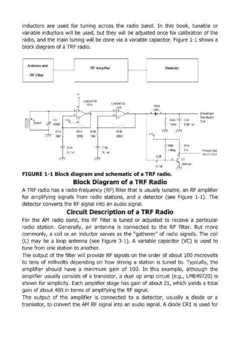
radio, and the main tuning will be done via a variable capacitor. Figure 1-1 shows a
block diagram of a TRF radio.
Antenna and
RF Amplifier Detector
RF Filter
-v
LME49720
U1A LME49720 1N34
"" U18 CR1
7 2 Envelope
DetAudio
III • ~40Uh 365pf R~ 1 C1A Out
vc
lOOK
0.001 uf
R1A RFA R1B RFB
100 2000 100 2000
R18
1 ~:A"t 1 ~:8"t 2K Audio Out
Power Det
21114124
FIGURE 1-1 Block diagram and schematic of a TRF radio.
Block Diagram of a TRF Radio
A TRF radio has a radio-frequency (RF) filter that is usually tunable, an RF amplifier
for amplifying signals from radio stations, and a detector (see Figure 1-1). The
detector converts the RF signal into an audio signal.
Circuit Description of a TRF Radio
For the AM radio band, the RF filter is tuned or adjusted to receive a particular
radio station. Generally, an antenna is connected to the RF filter. But more
commonly, a coil or an inductor serves as the "gatherer" of radio signals. The coil
(L) may be a loop antenna (see Figure 3-1). A variable capacitor (VC) is used to
tune from one station to another.
The output of the filter will provide RF signals on the order of about 100 microvolts
to tens of millivolts depending on how strong a station is tuned to. Typically, the
amplifier should have a minimum gain of 100 .. In this example, although the
amplifier usually consists of a tranSistor, a dual op amp circuit (e.g., LME49720) is
shown for simplicity. Each amplifier stage has gain of about 21, which yields a total
gain of about 400 in terms of amplifying the RF signal.
The output of the amplifier is connected to a detector, usually a diode or a
tranSistor, to convert the AM RF signal into an audio signal. A diode CRI is used for