
Page 20 - Build Your Own Transistor Radios a Hobbyists Guide to High-Performance and Low-Powered Radio Circuits
P. 20
t
Antenna RF Filter RF Amplifier and Det
Audio Out
+ V
R2
1 K
VC RF Antenna Coil!
T1
(I')
R1 C2
11~_------,A.udiO Out
2 500K .01 ut
C1
'------t Audio Transformer
.01 uf
(I') Q11
2
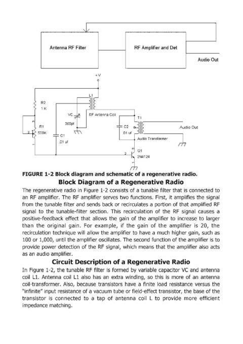
FIGURE 1-2 Block diagram and schematic of a regenerative radio.
Block Diagram of a Regenerative Radio
The regenerative radio in Figure 1-2 consists of a tunable filter that is connected to
an RF amplifier. The RF amplifier serves two functions. First, it amplifies the signal
from the tunable filter and sends back or recirculates a portion of that amplified RF
signal to the tunable-filter section. This recirculation of the RF signal causes a
positive-feedback effect that allows the gain of the amplifier to increase to larger
than the original gain. For example, if the gain of the amplifier is 20, the
recirculation technique will allow the amplifier to have a much higher gain, such as
100 or 1,000, until the amplifier oscillates. The second function of the amplifier is to
provide power detection of the RF signal, which means that the amplifier also acts
as an audio amplifier.
Circuit Description of a Regenerative Radio
In Figure 1-2, the tunable RF filter is formed by variable capacitor VC and antenna
coil L1. Antenna coil Ll also has an extra winding, so this is more of an antenna
coil-transformer. Also, because transistors have a finite load resistance versus the
"infinite" input resistance of a vacuum tube or field-effect transistor, the base of the
transistor is connected to a tap of antenna coil L to provide more efficient
impedance matching.