
Page 22 - Build Your Own Transistor Radios a Hobbyists Guide to High-Performance and Low-Powered Radio Circuits
P. 22
signal. So although reflex radios have similar characteristics as regenerative radios,
they are not the same. Reflex radios do not recirculate RF signals back to the
amplifier. And unlike regenerative radios, reflex radios do not have a regeneration
control to increase the gain of the amplifier. A reflex radio would be essentially the
same as a TRF radio but with use of a recirculation technique to amplify audio
signals. Thus, in terms of sensitivity and selectivity, a reflex radio has the same
performance as a TRF radio (Figure 1-3).
L L
I -WI eve
~ Audio
RF Ant;enna Filter RF/AF Amplifier Det
-
Audio Out
+v
CR1
+ V 5
1N34 R2
Cl 8 10 K
RF Transformer 1+
+
R1 10 uf
T1
100 K
C3 ~ Audio Out
C2 .01 uf
- l Audio Transformer 1
01 u
('I")
2
RF Antenna Coil
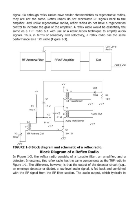
FIGURE 1 ... 3 Block diagram and schematic of a reflex radio.
Block Diagram of a Reflex Radio
In Figure 1-3, the reflex radio consists of a tunable filter, an amplifier, and a
detector. In essence, this reflex radio has the same components as the TRF radio in
Figure 1-1. The difference, however, is that the output of the detector circuit (e.g.,
an envelope detector or diode), a low-level audio signal, is fed back and combined
with the RF signal from the RF filter section. The audio output, which typically in