Page 27 - Build Your Own Transistor Radios a Hobbyists Guide to High-Performance and Low-Powered Radio Circuits
P. 27

To Olan 1 Sound Card
                                                              1------------1  I Amplifier
                                                  Quadrature
                   Wide-Band RF Filter
                                     t-------I
                                                    Mixer                                   To Chan 2 Sound Card
                                                            Q 1------------1 Q Amplifier


                                                 Two-Phase
                                                   Oscillator
                                                                                     +Y


                                                                                           1  To Chan 1 Sound Card


                                                           C-,n Phase J       R4A        R5A

                            L1
                                                   U28                        100        10 K
                                                  74HC4066
                           Y1  XTAL                                        T  C3A
              ~---~D~----~                                                rh' uf
                        +v                                                                 7  To Chan 2 Sound Card

                                                                                        U3B
                                     R2             Flip Flop                 R4B        R58
                                                    Oock In                   100        10 K
                C2                   1K  T C3
             T                             22Pt                               C3B
            rl-/2 pt                   rh                                  T 11Uf
                          1Meg                                            m
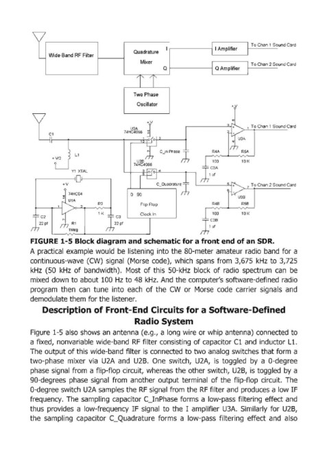
            FIGURE 1-5 Block diagram and schematic for a front end of an SDR.
            A practical  example would  be  listening  into the SO-meter amateur radio  band  for a

            continuous-wave  (CW)  signal  (Morse  code),  which  spans  from  3,675  kHz  to 3,725
            kHz  (50  kHz  of bandwidth).  Most  of this  50-kHz  block  of radio  spectrum  can  be
            mixed  down to about 100  Hz to 48  kHz.  And  the computer's software-defined  radio
            program  then  can  tune  into  each  of the  CW  or  Morse  code  carrier  signals  and
            demodulate them for the listener.

                Description of Front-End Circuits for a Software-Defined
                                                  Radio System

            Figure  1-5 also shows an  antenna (e.g., a long wire or whip antenna) connected  to
            a fixed,  nonvariable  wide-band  RF  filter consisting  of capacitor Cl and  inductor Lt.
            The output of this wide-band filter is connected to two analog  switches that form  a
            two-phase  mixer  via  U2A  and  U2B.  One  switch,  U2A,  is  toggled  by  a  O-degree

            phase signal  from  a flip-flop circuit,  whereas the other switch,  U2B,  is toggled  by a
            gO-degrees  phase  signal  from  another  output terminal  of the  flip-flop  circuit.  The
            O-degree switch U2A samples the RF signal from the RF filter and  produces a low IF
            frequency.  The  sampling  capaCitor C_InPhase  forms a low-pass filtering  effect and
            thus  provides  a  low-frequency  IF signal  to  the  I  amplifier  U3A.  Similarly  for  U2B,
            the  sampling  capacitor  C_Quadrature  forms  a  low-pass  filtering  effect  and  also
   22   23   24   25   26   27   28   29   30   31   32