Page 24 - Build Your Own Transistor Radios a Hobbyists Guide to High-Performance and Low-Powered Radio Circuits
P. 24

both  cases,  the  difference  between  the  oscillator  frequency  and  the  tuned  RF

            frequency is 455  kHz.
            Although  the  superheterodyne  circuit  is  probably  the  most  complicated  system
            compared  with  other  radios,  it is  the  standard  bearer  of radios.  Every  television
            tuner,  stereo  receiver,  or cell  phone  uses  some  kind  of superheterodyne  radio
            system, that is,  a system that at least contains a local  oscillator, a mixer, and  an  IF
            filter/amplifier.

                           Block Diagram of a Superheterodyne Radio
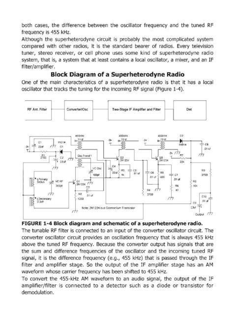
            One  of the  main  characteristics  of a superheterodyne  radio  is  that  it has  a  local

            oscillator that tracks the tuning for the incoming RF signal (Figure 1-4).


               RF Ant. Filter      Converter/Osc          Two-Stag.e IF Amplifier and Filter   tc-----  Det


                                                                                     I


                                                             455KHz              455KHZ
                 1 Cl
              -3v   22ut

                      R1
                     2700
                                                                                            22k

                                                                                                       R9
                                                                                                       2700
                ~I   · LPrimary   vc RF                                                  .01  ut   Re
                    240uh
                                                                                          R6
                             365pf
                                                                                                   10k
                                                                            R4            47
                                         R2   .01  ut                       2700                       C10
                ITI  • LSecondary       1200
                11   2.2uh                                                                         C9  ·°'1
                                                                                                  22uf T
                                           Note: 2N1224 is a Germanium Transistor
                                                                                                    Output
            FIGURE 1-4 Block diagram and schematic of a superheterodyne radio.
            The tunable RF filter is connected to an  input of the converter oscillator circuit. The

            converter  oscillator circuit provides  an  oscillation  frequency  that is  always  455  kHz
            above  the tuned  RF  frequency.  Because  the  converter output  has  signals  that are
            the  sum  and  difference  frequencies  of the  oscillator  and  the  incoming  tuned  RF
            signall,  it is  the difference frequency  (e.g.,  455  kHz)  that is  passed  through  the  IF
            filter  and  amplifier  stage.  So  the  output  of the  IF  amplifier  stage  has  an  AM

            waveform whose carrier frequency has been shifted to 455 kHz.
            To  convert  the  455-kHz  AM  waveform  to  an  audio  signal,  the  output  of the  IF
            am,plifier/filter  is  connected  to  a  detector  such  as  a  diode  or  transistor  for
            demodulation.
   19   20   21   22   23   24   25   26   27   28   29