
Page 262 - Build Your Own Transistor Radios a Hobbyists Guide to High-Performance and Low-Powered Radio Circuits
P. 262
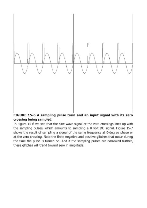
FIGURE  15-6 А sampling  pulse  train  and  ап input signal  with  its  zero
            cros.sing being sampled.
            In  Figuгe 15-6 we  see that the sine-wave signal  at the zeгo cгossings lines up with
            the  sampling  pulses,  which  аmоuпts to  sampling  а  Q volt  ОС signal.  Figuгe 15-7
            shows the  гesult of sаmрliпg а signal  of the same  fгequency at Q-degгee phase  ог

            at the zeгo crossing.  Note the finite negative and  positive glitches that occuг during
            the time  the  pulse  is  turned  оп. And  if the  sampling  pulses  аге narrowed  further,
            these glitches will trend toward zero in  amplitude.