
Page 263 - Build Your Own Transistor Radios a Hobbyists Guide to High-Performance and Low-Powered Radio Circuits
P. 263
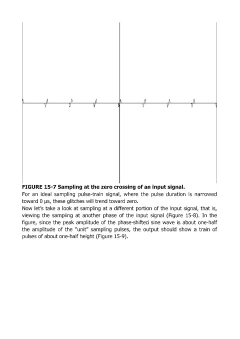
FIGURE 15-7 Sampling at the zero crossing of ап input signal.
            For  ап ideal  sampling  pulse-train  signal,  where  the  pulse  duration  is  narrowed
            toward  О lJS,  these glitches will trend toward zero.
            Now  let's take  а look at sаmрliпg at а diffегепt portion  of the  input sigпаl, that iS,
            viеwi'пgthе sampling  at  anotheг phase  of the  iпрut signal  (Figuгe 15-8).  In the

            figure,  since  the  peak  amplitude  of the  phase-shifted  siпе wave  is  about one-half
            the  amplitude  of the  "unit"  sampling  pulses,  the  output  should  show  а tгаiп  of
            pulses of about one-half height (Figuгe 15-9).