
Page 265 - Build Your Own Transistor Radios a Hobbyists Guide to High-Performance and Low-Powered Radio Circuits
P. 265
,..,
г'
1:
!
l'
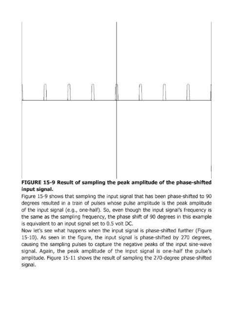
FIGURE 15-9 Result of sampling the peak amplitude of the phase-shifted
input signal.
Figuгe 15-9 shows that sampling the input signal that has Ьееп phase-shifted to 90
degгees гesu lted in а tгai n of pulses whose pulse amplitude is the peak amplitude
of the input signal (e.g., one-half). 50, even though the input signal's fгequency is
the same as the sampling f:requency, the phase shift of 90 degrees in this example
is equivalent to ап input signal set to 0.5 volt DC.
Now let's see what happens when the input signal is phase-shifted fuгther (Figure
15-10). As seen in the figuгe, the input signal is phase-shifted Ьу 270 degгees,
causing the sampling pulses to capt1ure the negative peaks of the input sine-wave
signal. Аgа i п, the peak amplitude of the i прut signal is one-half the pulse's
amplitude. Figuгe 15-11 shows the гesult of saimpling the 270-degгee phase-shifted
signal.