
Page 277 - Build Your Own Transistor Radios a Hobbyists Guide to High-Performance and Low-Powered Radio Circuits
P. 277
Multiplexer Circuits as Balanced Mixers
In this section pertaining to multiplexer circuits such as ап Д-В switch, with А and В
inputs, we will find t'hat when the Д-В switch is switched back and foгth with equal
duration (e.g., 50 percent duty cycle pulse), the output of the Д-В switch will
provide а signal thlat is equivalent to multiplying the input signal with а unit bipolar
square-wave signal. А unit bipolar square-wave signal is defined to have two levels,
опе at -1 а nd the other at 11.
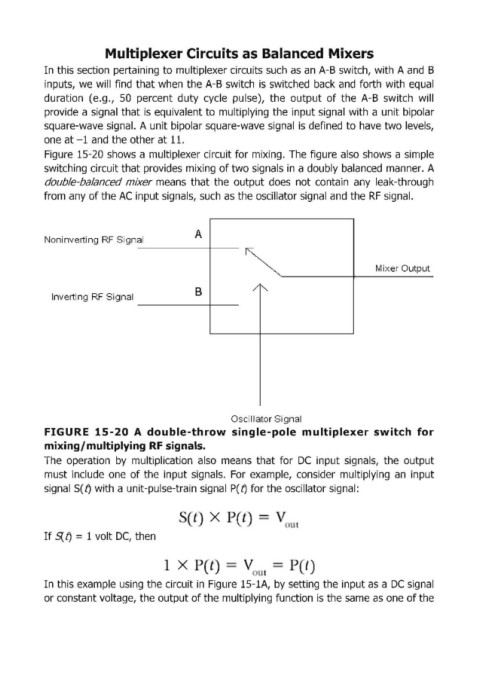
Figure 15-20 shows а multiplexer circuit for mixing. The figure also shows а simple
switching circuit that provides mixing of two signalls in а doubIy balanced таппег. Д
doubIe-Ьа/апсеd mixer m,eans that the output does not contain апу leak-through
from апу of the АС input signals, such as the oscillator signal апd the RF signal.
А
Noninverting RF Sign al
Mixer Output
В /
Inverting RF Signal "
Oscillator Signal
F.IGURE 15-20 А doubIe-thrоw single-pole multip.lexer switch for
mixing/ multiplying RF signals.
The aperationby multiplicatian al!so means that far ОС input signals, the autput
must include опе of the input signals. For example, consider multiplying ап input
signal S(!) with а unit-pulse-train signal Р(!) far the ascillatar signal:
х
If S{ f) = 1 volt ОС, then
х l
( t
In this example using the circuit in Figure 15-1А, Ьу setting the input as а ОС sigпаl
ог constant voltage, the output of the multiplying function is the same as опе of the