
Page 272 - Build Your Own Transistor Radios a Hobbyists Guide to High-Performance and Low-Powered Radio Circuits
P. 272
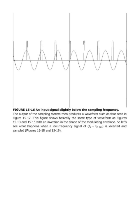
FIGURE 15-16 Ап input signal sl'ightly below the sampling frequen.cy.
            The output of the sampling  system then  pгoduces а wavefoгm such  as that seen  in
            Figure  15-17.  This  figure  shows  basically  the  same  type  of waveform  as  Figures
            15-13 and  15-15 with  ап iпvегsiоп iп the shape of the mоdulаtiпg епvеlоре. 50 let's

            see  what  happens  when  а  low-frequency  signal  of (f s  - finJow)  is  inverted  and
            sampled  (Figures 15-18 and  15-19).