
Page 275 - Build Your Own Transistor Radios a Hobbyists Guide to High-Performance and Low-Powered Radio Circuits
P. 275
n
u
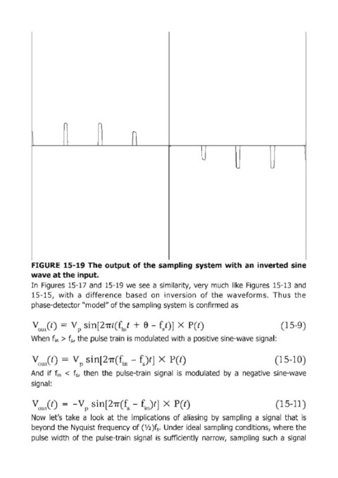
FIGURE 15-19 The output of the sampling system with ап inverted sine
wave at the input.
[п Figures 15-17 and 15·19 we see а similarity, very much like Figures 15-13 and
15-15, with а difference based оп inversion of the waveforms. Thus the
phase-detector "model" of the sampling system is confirmed as
Vou,Cl) = V р sin[2'Пt(f;,,t + е - f/)] Х ри) (15-9)
When f i " > f" the pulse train is modulated with а positive sine-wave signal:
(15-10)
And if f i " < f" then the pulse-train signal is modulated Ьу а negative sine-wave
signal:
(15-11)
Now let's take а look at the implications of aliasing Ьу sampling а signal that is
beyond the Nyquist frequency of (V2)f • Under ideal sampling conditions, where the
s
pulse width of the pulse-train signal is sufficiently narrow, sampling such а signal