
Page 286 - Build Your Own Transistor Radios a Hobbyists Guide to High-Performance and Low-Powered Radio Circuits
P. 286
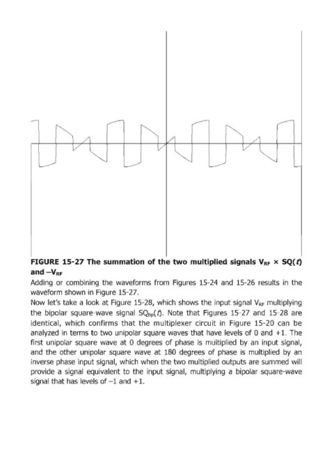
FIGURE  15-27 The  summation  of the two multiplied  signals V RF  х SQ( t)

            and -V RF
            Adding  ог combining  the  waveforms  from  Figures  15-24  and  15-26  results  in  the

            waveform shown in  Figure  15-27.
            Now  let's take  а look at Figure  15-28, which  shows the input signal  VRF  multiplying
            thle  bipolar  square-wave  signal  SQbp(t).  Note  that  Figures  15-27  and  15-28  аге

            identical,  which  confirms  that  the  multiplexer  circuit  in  Figure  15-20  сап Ье
            an,alyzed  in  terms to two  unipolar square  waves that have  levels of О and: + 1.  The
            first  unipolar  square  wave  at Odegrees  of phase  is  multiplied  Ьу ап input signal,
            and  the  other  unipolar  square  wave  at  180  degrees  of phase  is  multiplied  Ьу ап
            inverse phase  input signal,  which  when the two multiplied outputs аге summed  will
            provide  а signal  equivalent to  the  input signal,  multiplying  а bipolar  square-wave

            signal that has levels of -1 and  +1.