
Page 287 - Build Your Own Transistor Radios a Hobbyists Guide to High-Performance and Low-Powered Radio Circuits
P. 287
,
- r-- ------ ------
"" /1 ~ ~/
/1
" v v v "
~ ~ ~
L...---- L...---- ~ -
.; 5 . . .
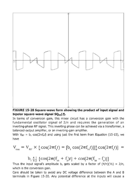
FIGURE 15-28 Square-wave form showlng the product of IПрut slgnal and
bipolar square-wave signal SQbp( t:).
[п terms of conversion gain, this mixer circuit has а conversion gain with the
fundamental oscillator signal of 2/ п and requires the generation of ап
inverting'phase RF signal. This inverting phase сап Ье achieved via а transformer, а
balanced'output amplifier, ог ап inverting-gain amplifier.
With V. F = Ь, cos(2nif, 1J and using just the first term from Equation (15'15), we
have
Ь, ~~ { cos[27f(~11 + fJt] + cos[27f(~11 - fs)J}
Thus the input signal's amplitude Ь, gets scaled Ьу а factor of (4/П)('/2 ) = 2/п,
which is the conversion gain.
Саге should Ье taken to avoid апу ОС voltage difference between the А and В
terminals in Figure 15·20. Апу potential difference at the inputs will cause а