
Page 45 - Build Your Own Transistor Radios a Hobbyists Guide to High-Performance and Low-Powered Radio Circuits
P. 45
B c
E
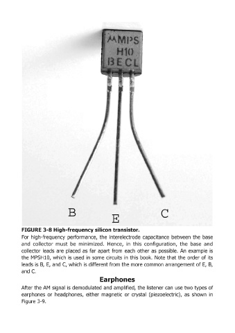
FIGURE 3-8 High-frequency silicon transistor.
For high-frequency performance, the interelectrode capacitance between the base
and collector must be minimized. Hence, in this configuration, the base and
collector leads are placed as far apart from each other as possible. An example is
the MPSH10, which is used in some circuits in this book. Note that the order of its
leads is B, E, and C, which is different from the more common arrangement of E, B,
and C.
Earphones
After the AM signal is demodulated and amplified, the listener can use two types of
earphones or headphones, either magnetic or crystal (piezoelectric), as shown in
Figure 3-9.