
Page 49 - Build Your Own Transistor Radios a Hobbyists Guide to High-Performance and Low-Powered Radio Circuits
P. 49
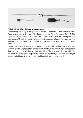
FIGURE 3-15 Film-dielectric capacitors.

            The  markings on  many frlm  capacitors are done in two ways.  One  is  in  microfarads.
            Thus the capacitor at the top of the figure is  marked ".010," meaning 0.01  IJF.  The
            capacitors at the bottom of the figure are  usually marked  with a three-digit code in
            picofarads (pF), with the third  digit denoting the number of zeros following  the first
            two  digits.  For  example,  "102"  means  10  plus  two  zeros  after  10  = 1,000  pF  or

            0.001  IJF.
            Ceramic,  mica,  and  film  capacitors can  be  connected  with the leads either way.  But
            common electrolytic capacitors are polarized and thus are notthe type of capacitors
            that can  have  leads  switched  without a problem.  The  schematic  diagram  will  point
            out  how  the  electrolytic  capacitors  should  be  connected.  See  the  electrolytic

            capacitors in Figure 3-16, where the markings indicate negative or (-).