
Page 48 - Build Your Own Transistor Radios a Hobbyists Guide to High-Performance and Low-Powered Radio Circuits
P. 48
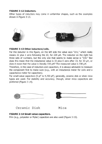
FIGURE 3-12Inductors.

            Other  types  of inductors  may  come  in  unfamiliar  shapes,  such  as  the  examples
            shown in  Figure 3-13.


            FIGURE 3-13 Other inductors/coils.

            For  the  inductor  in  this  figure,  on  the  left side  the  value  says  "221," which  really
            means  22  plus  1 zero  following  the  22,  for  220  IJH.  The  inductor on  the  right has
            three  sets  of numbers,  but the  only  one  that  seems  to  make  sense  is  "330." But
            does this  mean  that the  inductance value  is  33  plus  0 zero  after 33,  for 33  IJH,  or
            does it mean that the value is literally 330 IJH? The measured value is 330 JjH.
            Therefore,  in the case of inductors and  capacitors,  it is always advisable to measure

            the  component  first to  make  sure  (e.g.,  with  an  inductance  meter for  coils  and  a
            capacitance meter for capacitors).
            For small-value capacitors (5  pF to 4,700  pF),  generally, ceramic disk or silver mica
            types  are  used.  For  stability  and  accuracy,  though,  silver  mica  capacitors  are
            preferred (Figure 3-14).


                    Ceramic  Disk                                    Mica


            FIGURE 3-14 Small-value capacitors.
            Film  (e.g., polyester or Mylar) capacitors are also used (Figure 3-15).