
Page 77 - Build Your Own Transistor Radios a Hobbyists Guide to High-Performance and Low-Powered Radio Circuits
P. 77
To increase sensitivity and selectively, it is important to provide minimal loading to
a parallel inductor capacitor tank circuit. For an amplifier connected to the parallel
inductor capacitor circuit, this means as high an input resistance as possible. For
example, an amplifier whose input resistance is at least 100 k
n
would be acceptable in not loading down the Q of the inductor capacitor tank
circuit. Another alternative is to provide a tap in the coil, which allows connecting to
circuits or amplifiers with less than 100 k
n
of input resistance.
As the first TRF radio design is shown, you will see the principle of tapped-down
coils to preserve the high Q of the coil but also provide other beneficial
characteristics, such as avoiding oscillation.
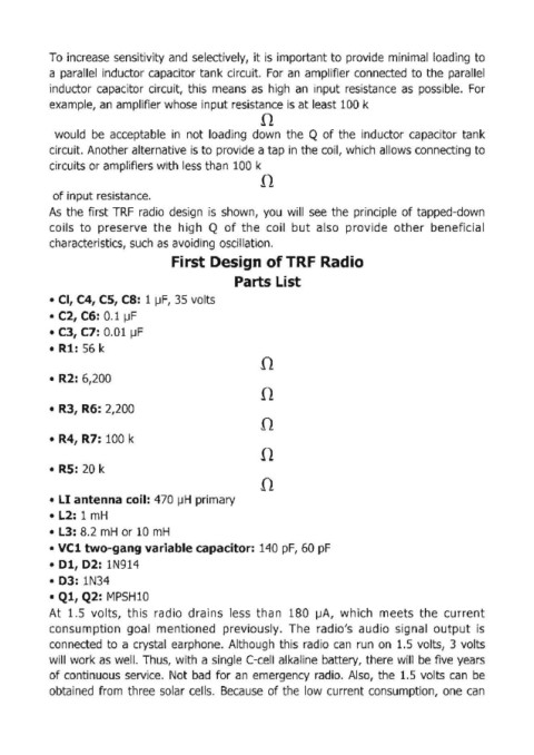
First Design of TRF Radio
Parts List
• Cl, C4, CS, C8: 1 ~F, 35 volts
• C2, C6: 0.1 ~F
• C3, C7: 0.01 ~F
• Rl: 56 k
n
• R2: 6,200
n
• R3, R6: 2,200
n
• R4, R7: 100 k
n
• Rs: 20 k
n
• LI antenna coil: 470 ~H primary
• L2: 1 mH
• L3: 8.2 mH or 10 mH
• VCl two-gang variable capacitor: 140 pF, 60 pF
• Dl, D2: 1N914
• D3: 1N34
• Ql, Q2: MPSHlO
At 1.5 volts, this radio drains less than 180 ~A, which meets the current
consumption goal mentioned previously. The radio's audio signal output is
connected to a crystal earphone. Although this radio can run on 1.5 volts, 3 volts
will work as well. Thus, with a single (-cell alkaline battery, there will be five years
of continuous service. Not bad for an emergency radio. Also, the 1.5 volts can be
obtained from three solar cells. Because of the low current consumption, one can