Page 78 - Build Your Own Transistor Radios a Hobbyists Guide to High-Performance and Low-Powered Radio Circuits
P. 78

wire a fruit/vegetable  battery  using  two  lemons  or potatoes  for this  radio.  Just  be

            sure  not to eat (consume)  any of the fruits or vegetables that are  used  for making
            the battery.
            In terms of construction, try to keep the base lead of transistor Q1  (MPSH 10) to the
            Ll  antenna  coill's  secondary  lead  short.  The  secondary  winding  of Ll  typically  has
            about  one-eighth  the  turns  of the  primary  winding.  Also,  to  avoid  "recirculation"
            from  the  a!mplified  RF  signal  back  to  antenna  coil  L1,  both  inductors  L2  and  L3

            should be mounted preferably at 90 degrees to the antenna coil.
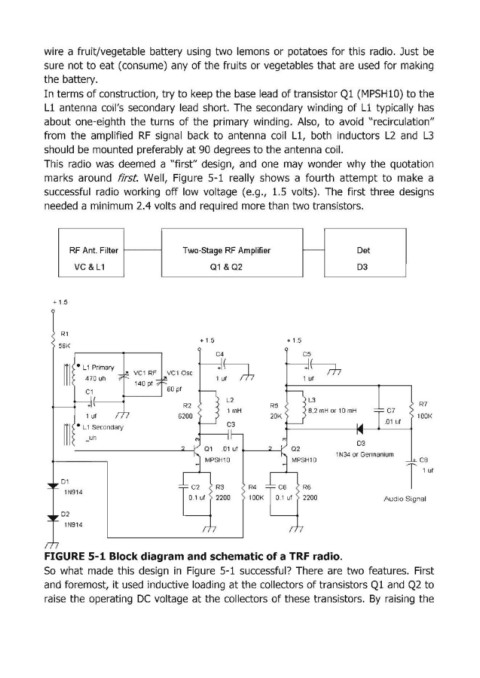
            This  radio  was  deemed  a "first" design,  and  one  may  wonder  why  the  quotation
            marks  around  first  Well,  Figure  5-1  really  shows  a  fourth  attempt  to  make  a
            successful  radio  working  off low  voltage  (e.g.,  1.5  volts).  The  first  three  designs
            needed a minimum 2.4 volts and  required more than two transistors.


                  RF Ant. Filter               Two-Stage RF Amplifier        f---         Det

                    VC &L1                           01  &02                              D3


              + 1.5


                Rl
                                                   + 1.S                + 1.S
                56K
                                                       C4                   CS
                                                       +!
                                                        I ~
                    ·  L  1  Primary                                         +t--m
                                  VCl  RF   VC10se
                      470 uh                           1 ut                  1 ut
                 111               140 pf
                                           60 pr
                                                         L2                   L3
                                               R2                   R5                                   R7
                                                          1 mH                8.2 mH  or HJ  mH
                                             6200                                                        lOOK

                                                                                          03
                                              2         .01  Uf  t-- 2 =--.f
                                                                                     1 N34  or Germanium


                01
                                                       R3      R4           R6
                 1 N914
                                                       2200    1!OOK        2200                 Audio Signal
                02
                 1N914


            FIGURE 5-1 Block diagram and schematic of a TRF radio.
            So  what  made  this  design  in  Figure  5-1  successful?  There  are  two features.  First
            and  foremost,  it used  inductive loading at the collectors of transistors Ql and  Q2  to

            raise the operating  DC  voltage  at the collectors  of these transistors.  By  raising  the
   73   74   75   76   77   78   79   80   81   82   83