
Page 83 - Build Your Own Transistor Radios a Hobbyists Guide to High-Performance and Low-Powered Radio Circuits
P. 83
• vel two-gang variable capacitor: 140 pF, 60 pF
• Dl, D2: 1N914
• D3: 1N34
• Ql, Q2, Q3: MPSH10
• Loop antenna (see Figure 3-2)
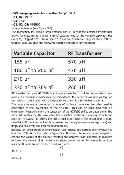
The motivation for using a loop antenna and T1 is that the antenna transformer
allows for matching to a wide range of capacitances for the variabl~e capacitor. For
example, T1 (part 42IF100) in Figure 5-2 has an inductance range of about 260 IJH
to about 570 J.JH. Thus the foUowing variable capacitors may be used:
Variable Capacitor - -ransfor .er
155· p,F 570 J.lH
180 pF to 200 pF 470, Il H
270 p,F 33,0 J.l H
330 pF to 365 pF ,260 J.l H
RF transformer part 42IF100 is actually an oscillator coil for superheterodyne
radios. But because it possesses, by coincidence, the proper turns ratio or tap, we
can use it in combination with a loop antenna to mimic a ferrite bar antenna.
The loop antenna is grounded on one of its leads, whereas the other lead is
connected to the lowest tap of the 42IF100. This can be confirmed with an
ohmmeter. Measuring from the center pin of the 42IF100 coil to an outer pin on the
same side of this coil, the lowest tap has a smaller resistance. Coupling the antenna
loop to the lowest tap allows the coil to maintain a high Q for acceptable to good
selectivity. If the antenna loop is connected to the higher-resistance tap, the Q will
drop, and selectivity will become unacceptable.
Because an extra stage of amplification was added, the current drain typically is
less than 250 IJA for the radio in Figure 5-2. However, the reader is encouraged to
change the values of the emitter resistors and collector load inductors or resistors
to lower the current drain while maintaining performance. For example, emitter
resistors R3 and R6 may be increased from 2.2 k
to 3.3 k
or 3.9 k