Page 84 - Build Your Own Transistor Radios a Hobbyists Guide to High-Performance and Low-Powered Radio Circuits
P. 84

while  load  inductors  L1  and  L2  are  increased  to  2.2  mH  to 4.7  mH  and  with  load

            resistors R2  and  R5  increased from 6,200


             to 20  k


            . Try one stage at a time with these suggested modifications.
                                    Author's Earllier TRF Designs

            As  stated  previously,  the  designs  from  Figures  5-1  and  5-2  actually  came  after
            designing  three  different TRF  radios  with  a  3-volt  supply.  At  that time,  all  three
            designs  used  only  resistor  loads  at  the  collectors  of the  transistor  voltage-gain

            amplifiers.  It wasn't until the reflex radios (with transfonmer and/or inductive loads)
            were designed for Chapter 6 that I  realized  that the answer to lower-voltage radios
            was  right  in front of me-use inductors for the load  instead of just resistors.
            So  sometimes  a  "final"  design  does  not always  have  a  straight  path,  but  the
            journey is still fun and exciting in terms of learning  new things ..

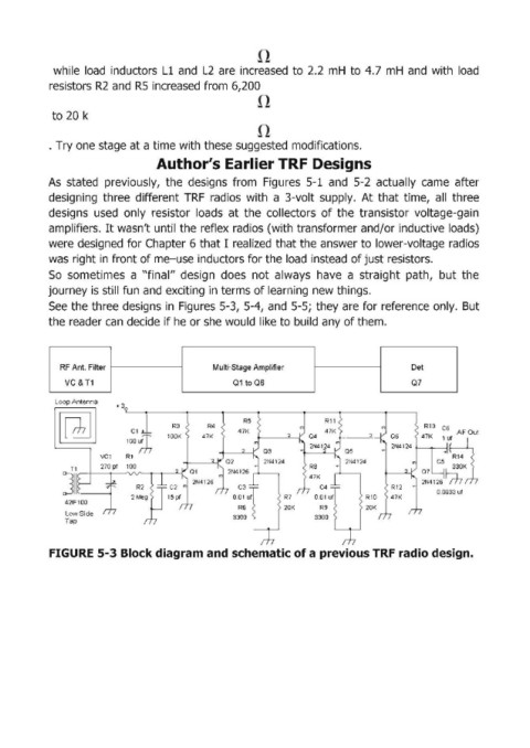
            See the three designs in Figures 5-3,  5-4,  and  5-5;  they are for reference only.  But
            the reader can  decide if he or she would  like to build any of them.


              RF Ant. Filter                     Multi-Stage Amplifier                        Det

                VC&T1                                 01 to 06                                Q7
             Loop Antenna
                           + 3

                                                                                                 R13  C6
                                                                                                47K  :UHR~:orn
                                                                  2

                                                                                                    C5
                                                                                                       330K
                                                                                                ~~4126 ~
                                                                                                    0.0033 uf
                                                                 R7
                                                                 20K
                Low Side
                Tap


            FIGURE 5-3 Block diagram and schematic of a previous TRF radio design.
   79   80   81   82   83   84   85   86   87   88   89