
Page 80 - Build Your Own Transistor Radios a Hobbyists Guide to High-Performance and Low-Powered Radio Circuits
P. 80
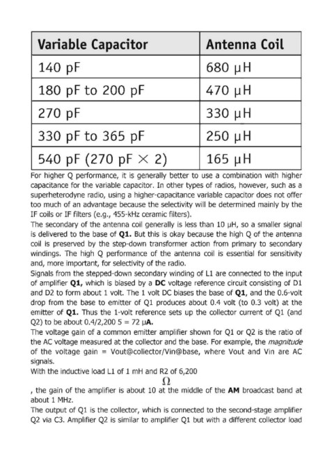
Variable 'Capacitor                                         Ante  na Coil


               140 p,F                                                     680IJ H


               180 pF to  200 pF                                           470~H


               270 P'                                                      330IJ H


               330 p,F to 3,65  pF                                         25'O(J H


               540  p,F (270 plF x  2)                                   I  165 11 H


            For  higher Q performance,  it  is  generally  better to  use  a combination  with  higher

            capacitance for the variable capacitor.  In other types of radios,  however,  such  as a
            superheterodyne radio,  using  a higher-capacitance variable capacitor does not offer
            too much  of an  advantage because the selectivity will  be  determined  mainly by the
            IF coils or IF filters (e.g., 455-kHz ceramic filters).

            The  secondary of the antenna  coil  generally is  less than 10  IJH,  so  a smaller signal
            is delivered to the  base  of Ql. But this is  okay  because the  high  Q of the antenna
            coil  is  preserved  by  the  step-down  transformer  action  from  primary  to  secondary
            windings.  The  high  Q  performance  of the  antenna  coil  is  essential  for  sensitivity
            and, more important, for selectivity of the radio.
            Signals from the stepped-down secondary winding  of Ll are connected  to the input
            of amplifier Ql, which  is  biased  by  a DC voltage  reference  circuit consisting  of Dl

            and  D2 to form about 1 volt.  The  1 volt DC  biases the base  of Ql, and the D.6-volt
            drop  from  the  base  to  emitter  of Ql  produces  about  0.4  volt (to  0.3  volt)  at the
            emitter  of Ql. Thus  the  l-volt reference  sets  up  the  collector  current of Ql  (and
            Q2) to be about 0.4/2,200 5 = 72  ~A.

            The voltage gain of a comm.on  emitter amplifier shown  for Q1  or Q2  is  the ratio of
            the AC voltage m,easured at the collector and the base.  For example, the magnitude
            of the  voltage  gain  = Vout@collector/Vin@base,  where  Vout  and  Vin  are  AC
            signa!ls.
            With the inductive load  L1  of 1 mH  and  R2  of 6,200


            , the gain  of the  ampllifier is about  10  at the  middle of the AM  broadcast  band  at

            about 1 MHz.
            The  output of Q1  is the collector,  which  is connected  to the second-stage amplifier
            Q2  via  C3.  Amplifier Q2  is  similar to amplifier Q1  but with a different collector load