
Page 103 - Build a Remote Controlled Robot
P. 103
70
CHAPTER FIVE
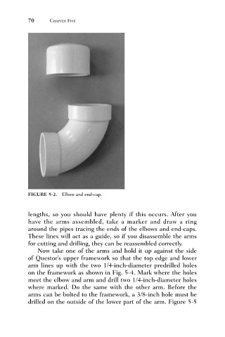
FIGURE 5-2. Elbow and end-cap.
lengths, so you should have plenty if this occurs. After you
have the arms assembled, take a marker and draw a ring
around the pipes tracing the ends of the elbows and end-caps.
These lines will act as a guide, so if you disassemble the arms
for cutting and drilling, they can be reassembled correctly.
Now take one of the arms and hold it up against the side
of Questor’s upper framework so that the top edge and lower
arm lines up with the two 1/4-inch-diameter predrilled holes
on the framework as shown in Fig. 5-4. Mark where the holes
meet the elbow and arm and drill two 1/4-inch-diameter holes
where marked. Do the same with the other arm. Before the
arms can be bolted to the framework, a 3/8-inch hole must be
drilled on the outside of the lower part of the arm. Figure 5-5