
Page 105 - Build a Remote Controlled Robot
P. 105
72
CHAPTER FIVE
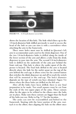
FIGURE 5-5. A 3/8-inch-diameter access hole.
shows the location of this hole. The hole which lines up to the
1/4-inch-diameter hole drilled previously is used to access the
head of the bolt so you can turn it with a screwdriver when
attaching the arm to the framework.
Three more holes must now be drilled in Questor’s left
arm to accommodate parts used in the drink dispenser. One of
the two 1/4-inch-diameter holes is drilled along the inside of
the lower section of the arm and allows a tube from the drink
dispenser to pass into the arm. The second 1/4-inch-diameter
hole is drilled on the underside of the arm just behind the
front end-cap. This hole is where the outlet spout of the dis-
penser is located. The final hole drilled in the arm is located
directly above the hole for the outlet spout on the top of the
arm behind the end-cap; it allows wires for the control button
that switches the drink dispenser on and off to reach the switch
that will be mounted in the end-cap. The hole’s diameter
depends on the type of switch you have obtained. Figure 5-6
shows where the three holes are drilled on the left arm.
After all the holes have been drilled, there is one final
preparation to be made. Two small squares must be cut from
the ends of the two upper pipes of the arms. These cutouts
allow for the pipes to be refitted to the elbows once the bolts
are in place. Make sure these cutouts are bigger than the head
of the bolts you use. Refer to Fig. 5-7 for the location.
The arms can now be reassembled and bolted to the
framework. Starting with the lower portion of the arm, reat-
tach it to the elbow, then aligning the hole on the elbow once