Page 211 - Buried Pipe Design
P. 211

Design of Pressure Pipes  185


         where D	   average diameter   b   a and t   thickness   b   a. Also,
                                       2
                                  2
                                            2
                                                 2
                            (b   a)   D	    b   a   2ab              (4.1b)
                                                           D	 2
                                 2
                      2
                                                       2
                           2
                                                  2
                                            2
                     b   a   D	   2ab ≈ D	   2 r   D
                                                            2
         Thus Eq. (4.1) can be rewritten using Eqs. (4.1a) and (4.1b) as follows:

                                          2
                                                  P i D
                                      P i (D	 /2)
                                max                                   (4.2)
                                        D 	t      2t
           Equation (4.2) is recognized as the equation for stress in a thin-
         walled cylinder (Fig. 4.2). This equation is sometimes called the
         Barlow formula, but is just a reduction from Lamé’s solution. This
         equation is the form most often recognized for calculating stresses due
         to internal pressure P .
                              i
           If the outside diameter D is the reference dimension, Eq. (4.2) can
                                   o
         be put into another form by introducing
                                     D D	   D o   t
           That is, the average diameter is equal to the outside diameter minus
         thickness. Equation (4.2) becomes
                                         P i (D o   t)
                                   max                                (4.3)
                                            2t


                                            t


                        P i


                               P D              P i D
                                i
                                           s max
                        D                        2t

            P i D                  P i D

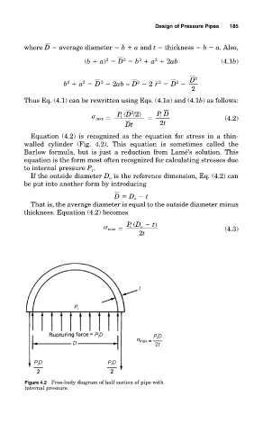
          Figure 4.2 Free-body diagram of half section of pipe with
          internal pressure.
   206   207   208   209   210   211   212   213   214   215   216