
Page 216 - Buried Pipe Design
P. 216
190 Chapter Four
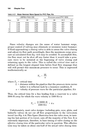
TABLE 4.2 Water Hammer Wave Speed for PVC Pipe, ft/s
(AWWA C900) DR Pressure-rated PVC SDR
Size 25 18 14 21 26 32.5 41
4 1106 1311 1496 1210 1084 967 859
6 1106 1311 1496 1210 1084 967 859
8 1106 1311 1496 1210 1084 967 859
10 1106 1311 1496 1210 1084 967 859
12 1106 1311 1496 1210 1084 967 859
Since velocity changes are the cause of water hammer surge,
proper control of valving may eliminate or minimize water hammer.
If fluid approaching a closing valve is able to sense the valve closing
and adjust its flow path accordingly, then the maximum surge pres-
sure as calculated from Eq. (4.6) may be avoided. To accomplish this,
the flow must not be shut off any faster than it would take a pres-
sure wave to be initiated at the beginning of valve closing and
returning again to the valve. This is called the critical time and is
defined as the longest elapsed time before final flow stoppage that
will still permit this maximum pressure to occur. This is expressed
mathematically as
2L
T cr
a
where T cr critical time
L distance within the pipeline that the pressure wave moves
before it is reflected back by a boundary condition, ft
a velocity of pressure wave for the particular pipeline, ft/s
Thus, the critical time for a line leading from a reservoir to a valve
3000 ft away for which the wave velocity is 1500 ft/s is
2 (3000) ft
T cr 4 s
1500 ft/s
Unfortunately, most valve designs (including gate, cone, globe, and
butterfly valves) do not cut off flow proportionate to the valve-stem
travel (see Fig. 4.4).This figure illustrates how the valve stem, in turn-
ing the last portion of its travel, cuts off the majority of the flow. It is
extremely important, therefore, to base timing of valve closing on the
effective closing time of the particular valve in question. This effective
time may be taken as about one-half of the actual valve closing time.