
Page 214 - Buried Pipe Design
P. 214
188 Chapter Four
D internal diameter of pipe, in
t wall thickness of pipe, in
E modulus of elasticity of pipe material, lb/in 2
C 1 constant dependent upon pipe constraints (C 1.0 for pipe
1
with expansion joints along its length)
For water at 60 F, Eq. (4.8) may be rewritten by substituting 1.938
2
3
slug/ft and K 313,000 lb/in .
4822
a (4.9)
1 (K /E)(D/t)C 1
Equations (4.6), (4.7), and (4.8) can be used to determine the magni-
tude of surge pressure that may be generated in any pipeline. The valid-
ity of the equations has been shown through numerous experiments.
Figure 4.3 is a plot of the pressure rise in pounds per square inch as
a function of velocity change for various values of wave speed. Tables 4.l
and 4.2 give the calculated wave speed according to Eq. (4.8) for ductile
iron and PVC pipe, respectively. In general, wave speeds vary from
3000 to 5000 ft/s for ductile iron and from 1200 to 1500 for PVC pipes.
Example Problem 4.1 Determine the magnitude of a water hammer
pressure wave induced in a 12-in class 52 ductile iron pipe and in a
class 235 DR 18 PVC pipe if the change in velocity is 2 ft/s.
solution From Tables 4.1 and 4.2 and Fig. 4.3:
Pipe Wave speed, ft/s
Class 52 DI 4038
Class 235 PVC 1311
The resulting pressure surges are
Pipe Surge pressure, lb/in 2
Class 52 DI 105
Class 235 PVC 35
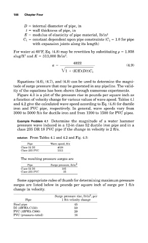
Some appropriate rules of thumb for determining maximum pressure
surges are listed below in pounds per square inch of surge per 1 ft/s
change in velocity.
2
Surge pressure rise, lb/in , per
Pipe 1 ft/s velocity change
Steel pipe 45
DI (AWWA C150) 50
PVC (AWWA C900) 20
PVC (pressure-rated) 16