
Page 281 - Buried Pipe Design
P. 281
252 Chapter Five
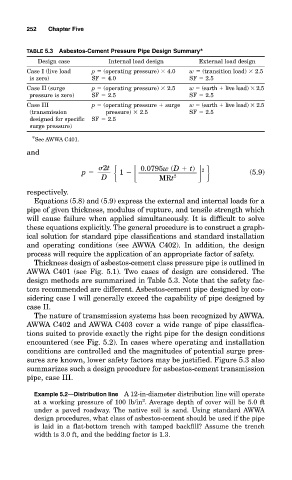
TABLE 5.3 Asbestos-Cement Pressure Pipe Design Summary *
Design case Internal load design External load design
Case I (live load p (operating pressure) 4.0 w (transition load) 2.5
is zero) SF 4.0 SF 2.5
Case II (surge p (operating pressure) 2.5 w (earth live load) 2.5
pressure is zero) SF 2.5 SF 2.5
Case III p (operating pressure surge w (earth live load) 2.5
(transmission pressure) 2.5 SF 2.5
designed for specific SF 2.5
surge pressure)
* See AWWA C401.
and
2t 0.0795w (D t)
p
1 (5.9)
2
D MRt 2
respectively.
Equations (5.8) and (5.9) express the external and internal loads for a
pipe of given thickness, modulus of rupture, and tensile strength which
will cause failure when applied simultaneously. It is difficult to solve
these equations explicitly. The general procedure is to construct a graph-
ical solution for standard pipe classifications and standard installation
and operating conditions (see AWWA C402). In addition, the design
process will require the application of an appropriate factor of safety.
Thickness design of asbestos-cement class pressure pipe is outlined in
AWWA C401 (see Fig. 5.1). Two cases of design are considered. The
design methods are summarized in Table 5.3. Note that the safety fac-
tors recommended are different. Asbestos-cement pipe designed by con-
sidering case I will generally exceed the capability of pipe designed by
case II.
The nature of transmission systems has been recognized by AWWA.
AWWA C402 and AWWA C403 cover a wide range of pipe classifica-
tions suited to provide exactly the right pipe for the design conditions
encountered (see Fig. 5.2). In cases where operating and installation
conditions are controlled and the magnitudes of potential surge pres-
sures are known, lower safety factors may be justified. Figure 5.3 also
summarizes such a design procedure for asbestos-cement transmission
pipe, case III.
Example 5.2—Distribution line A 12-in-diameter distribution line will operate
2
at a working pressure of 100 lb/in . Average depth of cover will be 5.0 ft
under a paved roadway. The native soil is sand. Using standard AWWA
design procedures, what class of asbestos-cement should be used if the pipe
is laid in a flat-bottom trench with tamped backfill? Assume the trench
width is 3.0 ft, and the bedding factor is 1.3.