Page 282 - Buried Pipe Design
P. 282

Rigid Pipe Products  253
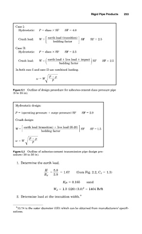

           Case I:
            Hydrostatic:  P   class   SF  SF   4.0

                               earth load (transition)
            Crush load:  W                       SF  SF   2.5
                                bedding factor
           Case II:
            Hydrostatic:  P   class   SF  SF   2.5
                               earth load   live load   impact
            Crush load:  W                            SF   SF   2.5
                                   bedding factor
           In both case I and case II use combined loading.

                              P   p
                      w   W
                               P
         Figure 5.1 Outline of design procedure for asbestos-cement class pressure pipe
         (6 to 16 in).


           Hydrostatic design:
           P   (operating pressure   surge pressure) SF  SF   2.0

           Crush design:
                 earth load (transition)   live load (H-20)
           W                                   SF    SF   1.5
                         bedding factor

                   P   p
           w   W
                    P
         Figure 5.2 Outline of asbestos-cement transmission pipe design pro-
         cedure (18 to 36 in).
           1. Determine the earth load.

                           H    5.0
                                       1.67  (from Fig. 2.2, C d   1.3)
                           B d  3.0
                                     K    0.165    sand
                                                 2
                                W d   1.3 (120) (3.0)   1404 lb/ft
           2. Determine load at the transition width. *


           * 13.74 is the outer diameter (OD) which can be obtained from manufacturers’ specifi-
         cations.
   277   278   279   280   281   282   283   284   285   286   287