
Page 57 - Buried Pipe Design
P. 57
External Loads 35
where the only new term is p, which is the intensity of the distributed
load in pounds per square foot. The load coefficient C s is a function of
D/(2H) and M/(2H), where D and M are the width and length, respec-
tively, of the area over which the distributed load acts. The values of
the impact factor F′ can be determined from Table 2.5 and the load
coefficient C s from Table 2.6.
Highway and railway loads
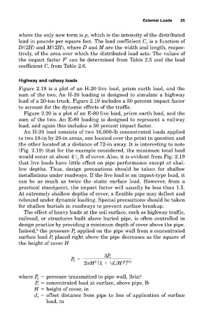
Figure 2.19 is a plot of an H-20 live load, prism earth load, and the
sum of the two. An H-20 loading is designed to simulate a highway
load of a 20-ton truck. Figure 2.19 includes a 50 percent impact factor
to account for the dynamic effects of the traffic.
Figure 2.20 is a plot of an E-80 live load, prism earth load, and the
sum of the two. An E-80 loading is designed to represent a railway
load, and again this includes a 50 percent impact factor.
An H-20 load consists of two 16,000-lb concentrated loads applied
to two 18-in by 20-in areas, one located over the point in question and
the other located at a distance of 72-in away. It is interesting to note
(Fig. 2.19) that for the example considered, the minimum total load
1
would occur at about 4 ft of cover. Also, it is evident from Fig. 2.19
2
that live loads have little effect on pipe performance except at shal-
low depths. Thus, design precautions should be taken for shallow
installations under roadways. If the live load is an impact-type load, it
can be as much as twice the static surface load. However, from a
practical standpoint, the impact factor will usually be less than 1.5.
At extremely shallow depths of cover, a flexible pipe may deflect and
rebound under dynamic loading. Special precautions should be taken
for shallow burials in roadways to prevent surface breakup.
The effect of heavy loads at the soil surface, such as highway traffic,
railroad, or structures built above buried pipe, is often controlled in
design practice by providing a minimum depth of cover above the pipe.
8
Indeed, the pressure P p applied on the pipe wall from a concentrated
surface load P s placed right above the pipe decreases as the square of
the height of cover H
3P s
P p
2 H [1 (d s/H) ]
2 5/2
2
where P p pressure transmitted to pipe wall, lb/in 2
P s concentrated load at surface, above pipe, lb
H height of cover, in
d s offset distance from pipe to line of application of surface
load, in