
Page 125 - CNC Robotics
P. 125
CNC Robotics
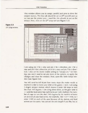
This w indow allows you to assign parallel port pins to drive the
stepper motors. The first tab sho uld be set to LPT parallel port so
we can use the printer port. I used the DLL already in use as the
default. Next, click on the LPT setup tab (see Figure 5 ,5).
..
Figure 5,5
LPT setup window.
':"i~
" ,
!~ ~
,f- .:I s_ oo l ,OlI !
; , .:l _ lOa I '01 I
1'_1_ _ 1
;: f.---.
J~ g ..J ",;;." 1
~~ :::;-.:: 1
~G ~ ~ ~.::;j
;J
.. ~
'O~
Z-Toct< J)v_,....
rei BI 7. I~EGJ ~m"!"I"1 @!"I ' ''~ ""'~ . "'~ .:J
I am using pi n 2 for x step and pi n 3 for x direction , pin 4 for y
step and pin 5 for y direction , pin 6 for z step and pin 7 for z direc-
tion . I also set the motor enable setting to "Always On." For test-
ing, you won 't need to set any more of the options, so apply the
cha nges and close the w indow. Next, open the Table Setup win-
dow (see Fig ure 5.6).
You will need to tell Kearn how many steps the motor needs to
receive in order to move your slide or the gantry I inch. I am using
2- degree stepper motors, w hich means it takes 180 steps to turn
the shaft 360 degrees. I am using direct drive, so the gear ratio is
I : 1 and the lead screw has eight turns per inch. Multip ly the num-
ber of steps to turn the shaft 360 degrees by the number of turns
on an inch of your lead screw. For examp le, 180 X 8 = 1440, so I
enter 1440 for each of the axes because all my motors and lead
screws are the same. You can set the axis length if you li ke, but at
116